Near-side drive
The inner hand-wheel connects directly to the rear wheel on the user's operating side.
Research and Design Intern
Formerly Arcatron Mobility
A year-long introduction to accessible product development that culminated in a prototype-ready concept for a foldable manual wheelchair that can be propelled and steered with one hand.

The Design Challenge
Hemiplegia can leave one side of the body paralyzed, making a standard self-propelled wheelchair difficult to use without assistance. Powered alternatives exist, but they add cost, weight, charging needs, and more components to maintain.
The goal was a fully mechanical chair that offered true one-hand propulsion and steering while staying lightweight, foldable, affordable, and familiar to manufacture.
How It Works
Two coaxial hand-wheels sit on the same side of the chair. They let the user control each rear wheel independently without reaching across the body or relying on motors and electronics.
The inner hand-wheel connects directly to the rear wheel on the user's operating side.
The outer hand-wheel sends torque through a compact transfer mechanism to the far rear wheel.
Pushing both inputs together moves straight; favoring either input creates the turning moment needed to arc or pivot.
CAD Evidence
These CAD views show the concept at the stage where the folding frame, rear wheel layout, caster packaging, and one-hand drive mechanism could be checked together as an assembly.
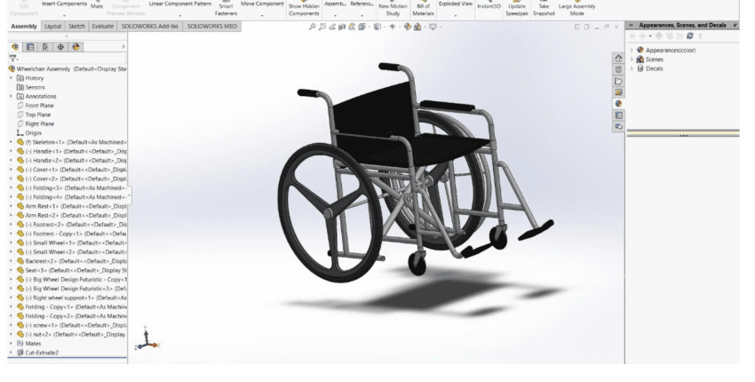
A complete wheelchair assembly used to evaluate the frame, folding members, footrests, caster placement, and hand-wheel layout.
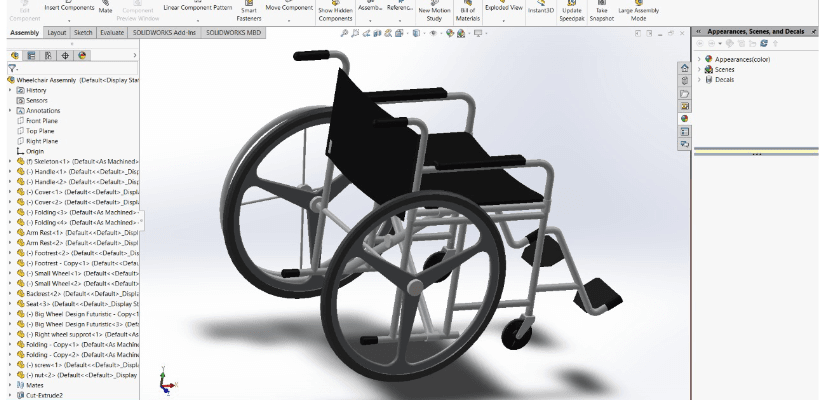
A closer side view showing the coaxial wheel layout and the space needed around the rear wheels and front caster modules.
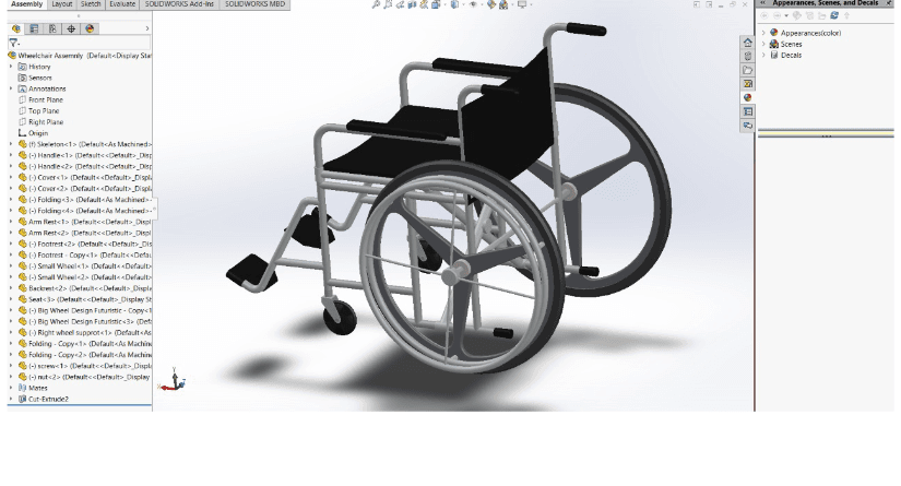
A rear three-quarter view used to reason through axle routing, hand-wheel reach, and the folding constraints around the chair frame.
Designing Around the Fold
An early through-axle blocked the wheelchair's folding path. Replacing it with a two-piece axle and coupler preserved alignment while allowing the chair to collapse.
The design reused parts and suppliers already familiar to the factory, reducing new tooling, simplifying service, and keeping the concept closer to production reality.
A low-spoke molded wheel was selected over a bicycle-style rim to balance manufacturing cost, user safety, durability, and practical load distribution.
C-clips, reachable rods and cables, standard caster modules, and familiar shop tolerances were retained so common repairs would not require specialized tools.
Before designing the chair, I followed the factory workflow from raw steel tube preparation through cutting, bending, tack welding, powder coating, final assembly, and quality inspection. That exposure made the CAD work more grounded in how parts are actually held, joined, checked, stored, repaired, and shipped.
SolidWorks became the main design environment for wheel, caster, frame, footrest, armrest, seat, axle, and folding assemblies. I also learned model slicing, PLA print preparation, nozzle and bed temperature setup, and three-axis printer calibration.
Supporting CAD Practice
Before tackling the wheelchair assembly, I practiced modeling common gear geometries in SolidWorks. The exercises developed comfort with revolves, sweeps, helixes, cuts, mirrors, and circular patterns.
Spur gear
Helical gear
Bevel gear
Herringbone gear
Worm gear
Outcome
I owned the concept from factory study through SolidWorks assemblies and bench-level validation, then presented it for internal prototyping. The company chose not to create a new SKU because regional demand was too narrow for a small manufacturer with portions of production outsourced.
The result was still a complete engineering proposal: a lightweight, mechanical solution that protected folding capability, reused existing parts, and prioritized predictable control and independent mobility.