ACRC Research

Flammable-fluid compressor load stand support.

I supported compressor testing infrastructure by helping turn electrical schematics into CAD enclosure layouts, instrumenting a smaller isobutane load stand, and running early leak, pressure, and data-acquisition checks.

Research Area

Compressor Testing

Working Fluid

Isobutane

Systems

Large and small load stands

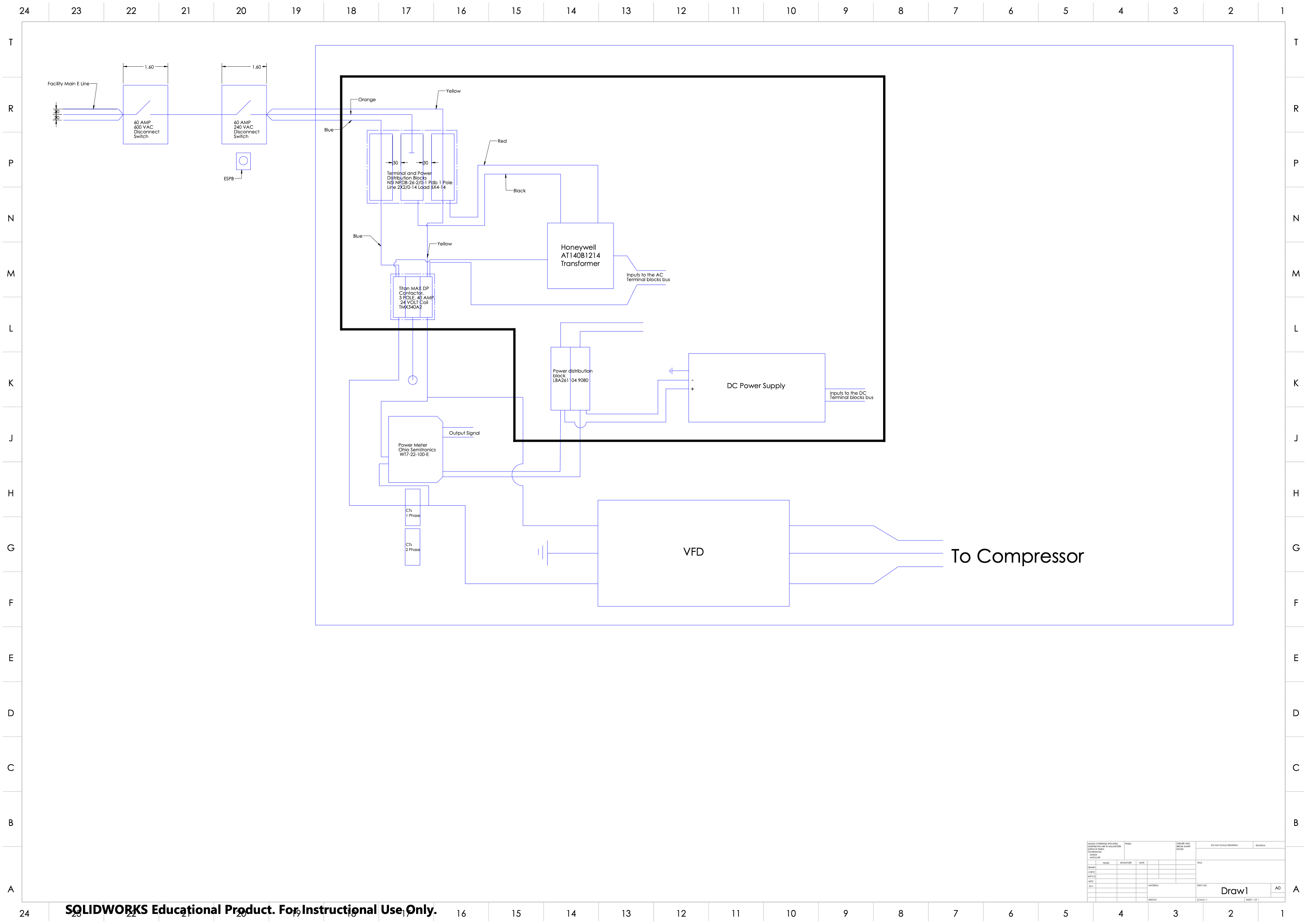
Electrical connection schematic for a compressor load stand
Electrical connection schematic used as the basis for enclosure-layout and packaging work on the larger compressor load stands.

My Role

Schematic work, CAD packaging, instrumentation, and test setup.

Electrical schematic to enclosure design

I helped develop the electrical schematic used for the large compressor load stands, then translated that layout into CAD-based electrical enclosures. The work connected disconnects, transformers, contactors, power distribution, VFD routing, and sensor/data pathways into physical packaging that could be reviewed and built.

Instrumentation on the isobutane stand

On the smaller flammable-fluid load stand, I helped mount temperature and pressure sensors at the required measurement points and prepared the tubing with insulating padding so the setup could produce more reliable thermal and pressure readings during checkout.

Pressure testing and LabVIEW checkout

Testing work included leak checks, pressure tests, and using LabVIEW to record pressure-sensor data. I adjusted valves during setup to move the stand toward expected pressures while monitoring the instrument response.

Why the smaller isobutane stand mattered.

Isobutane is flammable, so the smaller stand gave the lab a focused setup for carefully checking instrumentation, pressure behavior, and basic operating response before moving to higher-capacity equipment.

1

Mounted and checked pressure and temperature sensors on the smaller stand.

2

Applied insulating padding around copper tubing to reduce unwanted heat exchange with the room.

3

Performed leak testing and pressure testing before moving into refrigerant-side checkout.

4

Used LabVIEW to record pressure-sensor readings while valves were adjusted toward target operating conditions.

System Context

Compressor performance testing with safety built into the system.

The reference load-stand design was built around flammable refrigerants and compressor performance testing, with safety treated as a primary design driver.

The report describes a hot-gas-bypass architecture, pressure and temperature instrumentation, LabVIEW data acquisition, NI cRIO hardware, a VFD-driven compressor circuit, and hardwired safety controls.

Safety logic included pressure, temperature, water-flow, gas-detection, and emergency-stop inputs intended to de-energize the compressor path when a critical condition was detected.

Safety and instrumentation focus

The design review emphasized controlled compressor loading, reliable sensor data, and shutdown behavior for high-risk conditions such as gas detection, high pressure, high temperature, and water-flow loss.

Pressure switchesTemperature switchesGas detectionEmergency stopVFD shutdown

Evidence

Electrical layout work connected the schematic to buildable hardware.

The schematic shows the kind of power and control routing that had to be translated into enclosure geometry, component placement, conduit paths, and accessible service layout for the load-stand hardware.

Large-format electrical schematic for load stand compressor power and control connections
High-level electrical connections for the load stand, including power entry, disconnects, transformer, DC supply, VFD path, and compressor connection.

What this strengthened.

The work blended mechanical lab setup with electrical packaging and instrumentation, which made the project a useful bridge between CAD, testing, and research operations.

Electrical enclosure CAD
Schematic interpretation
Pressure instrumentation
Temperature instrumentation
LabVIEW data capture
Valve-based flow control
Leak and pressure testing
Flammable-fluid safety awareness