Mechanical design
I modeled the base and the Ender 3 hotend and extruder mounting bracket in Fusion 360, designing the bracket to mount both components at the arm tip.
ASME Product Development Team / Spring 2025
A low-cost, student-built 6-DOF robotic arm created to explore printing on curved and angled surfaces beyond conventional flat-layer systems.

The Build
The arm was developed as a mostly 3D-printed system using PLA and PETG, with standard nuts, bolts, and washers as the primary purchased hardware. Friction-fit hex pockets kept fasteners captive without heat-set inserts, which made assembly and rework quicker during a fast team build.
I modeled the base and the Ender 3 hotend and extruder mounting bracket in Fusion 360, designing the bracket to mount both components at the arm tip.
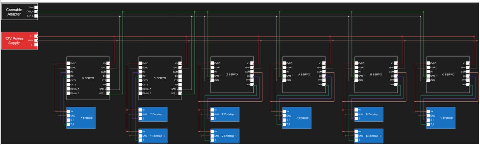
I soldered and assembled the electronics, daisy-chained six CAN-bus servos, connected joint endstops, and organized grounding at a central point in the base.
I helped turn the CAD into a functioning system, including sanding and Dremel work to correct print tolerancing issues before motion testing.
Extruder Mounting
I designed the extruder mounting bracket specifically around the Ender 3 hotend, extruder, and the tip geometry of the robotic arm. The goal was simple and practical: create a secure printed interface that mounted both components to the end of the mechanism while keeping the connection accessible and reasonable to remove during testing.
Assembly Planning
Beyond individual CAD parts, I worked through how the arm would actually come together on the bench. That meant planning fastening order, keeping tools clear of tight spaces, routing wires before joints became boxed in, and making sure printed parts could be replaced without tearing down the whole mechanism. When printed parts came out slightly tight or misaligned, I used sanding and Dremel work to fix tolerance issues and get the assemblies moving smoothly.
Mounting points stayed reachable after neighboring parts were installed.
Cable paths were planned before joints and covers boxed in the wiring.
The hotend, extruder, and printed modules could be removed for inspection.
Sanding and Dremel work corrected tight printed fits during assembly.
Controls and Wiring
Six servos were daisy-chained across CAN_H and CAN_L, with a 12 V supply and a USB-to-CAN adapter connecting the arm to a host computer. Joint endstops were routed to nearby controllers and the grounds met at a star point in the base to reduce loop problems.
Motion Testing
This phase focused on motion rather than print-quality or load characterization. ROS handled motion planning, while a lightweight serial connection carried commands to the arm.
Homed and jogged all six joints to verify motor direction, endstops, and zero positions.
Ran coordinated multi-joint moves along straight and curved paths while checking for stutter or faults.
Returned the arm to marked poses to evaluate repeatable positioning.
Checked small direction changes at the joints to understand backlash and repeatability.
Monitored the CAN network while all joints moved and confirmed termination at the two bus ends.
NovoPrint gave me experience carrying parts from an empty CAD file through printing, assembly, wiring, and system-level debugging. The biggest lesson was that good mechanical design includes the realities of fabrication, service access, wiring, and testing from the start.